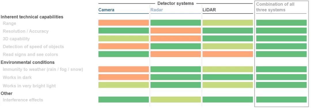
A giant leap is taking place in mobility. This is true whether in the automotive sector, where autonomous driving solutions are being developed, or in industrial applications using robotics and automated guided vehicles. The various components in the whole system must cooperate with each other and complement each other. The main goal is to create a seamless 3D view around the vehicle, use this image to calculate object distances and initiate the next move of the vehicle with the help of special algorithms. In fact, three sensor technologies are used at the same time here: LiDAR (LiDAR), radar, and cameras. Depending on the specific application scenario, these three sensors have their own advantages. Combining these advantages with redundant data can greatly improve security. The better these aspects are coordinated, the better the self-driving car will be able to navigate its environment.
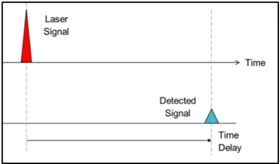
1. Direct Time of Flight (dToF):
In the time-of-flight approach, system manufacturers use the speed of light to generate depth information. In short, directed light pulses are fired into the environment, and when the light pulse hits an object, it is reflected and recorded by a detector near the light source. By measuring the time it takes for the beam to reach the object and return, the object distance can be determined, while in the dToF method the distance of a single pixel can be determined. The received signals are finally processed to trigger corresponding actions, such as vehicle evasion maneuvers to avoid collisions with pedestrians or obstacles. This method is called direct time-of-flight (dToF) because it is related to the exact "time-of-flight" of the beam. LiDAR systems for autonomous vehicles are a typical example of dToF applications.
2. Indirect Time of Flight (iToF):
The indirect time-of-flight (iToF) approach is similar, but with one notable difference. Illumination from a light source (usually an infrared VCSEL) is amplified by a dodging sheet and pulses (50% duty cycle) are emitted into a defined field of view.
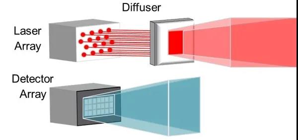
In the downstream system, a stored "standard signal" will trigger the detector for a period of time if the light does not encounter an obstacle. If an object interrupts this standard signal, the system can determine the depth information of each defined pixel of the detector based on the resulting phase shift and the time delay of the pulse train.
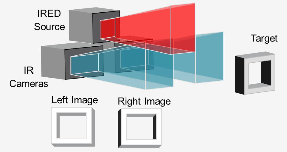
3. Active Stereo Vision (ASV)
In the "active stereo vision" method, an infrared light source (usually a VCSEL or IRED) illuminates the scene with a pattern, and two infrared cameras record the image in stereo.
By comparing the two images, downstream software can calculate the required depth information. Lights support depth calculations by projecting a pattern, even on objects with little texture such as walls, floors, and tables. This approach is ideal for close-range, high-resolution 3D sensing on robots and automated guided vehicles (AGVs) for obstacle avoidance.
Copyright @ 2020 Shenzhen Box Optronics Technology Co., Ltd. - China Fiber Optic Modules, Fiber Coupled Lasers Manufacturers, Laser Components Suppliers All Rights Reserved.